
APPLICATION OF 22KW SINUSOIDAL FILTER
SUMMARY
The most common application in the industry is driving asynchronous motors with variable frequency drives. Pulse-width modulation inverters are widely used for their high energy efficiency, motion accuracy, high starting torque, and low starting current. The high frequencies of the output voltage of the PWM inverter allow for a wider range of speed changes, increasing the efficiency and versatility of the variable frequency drive. However, they also generate high differential mode voltages (DM) and common mode currents (CM), along with reflected waves and rapid rising peak voltages (du/dt), which can lead to wear on motor winding insulation and damage to motor bearings. A major issue encountered in applications is difficulty driving the motor with a variable frequency drive over long-distance cable applications. To investigate this issue using a test method at our laboratory, we installed a three-phase 6-diode rectifier PWM inverter with 22 kW power – commonly used in industry – providing power to a 22 kW asynchronous motor through an unscreened 200 m cable length. This problem was then addressed by mounting a sinusoidal filter between the variable frequency drive and the asynchronous motor before supplying power to it.
INTRODUCTION
Asynchronous motors are commonly driven with variable frequency drives in the industry. The use of PWM inverter-based variable frequency drives is prevalent, as they offer high energy efficiency, precise motion control, strong starting torque, and low initial current draw. These devices are widely utilized in industry..

Figure-1: Variable Frequency Drive Diagram
PWM converters convert the DC voltage at the DC bus into AC voltage, improving motor speed control quality and increasing energy efficiency by accurately adjusting frequency and magnitude of the output voltage in a wide range. The circuit diagram of a standard three-phase motor drive is shown in Figure 1. The drive’s DC bus voltage is obtained by rectifying the grid voltage with a three-phase diode rectifier and then filtering it with capacitors.
The DC bus voltage is converted from DC to AC using a three-wire, three-phase inverter and applied to the motor terminals. Inverters are composed of semiconductor switches that operate in conduction or cut-off states similar to ideal switches during normal operation. As a result, the output voltages of inverters fed from a constant DC bus voltage take on rectangular waveforms. To achieve the desired amplitude and frequency of the output voltage, the switches are operated at specific frequencies and with a pulse pattern. Lower switching frequencies (below kHz) combined with small leakage inductances of the motor lead to strong harmonic components in the current flowing through it, resulting in vibration, noise, and losses. Consequently, efforts are made to increase switching frequency as much as possible within allowable switching losses limits. The 22kW power speed controller we tested features a 3-phase 6-diode rectifier and PWM inverter that operates at an output stage frequency of 6kHz.
The most commonly used technique for switching in inverters is pulse width modulation. This method involves generating a sinusoidal voltage at the fundamental frequency by adjusting the width of the inverter output voltage pulses, while using a fixed switching frequency (fs=1/Ts). To achieve this, a triangular wave (carrier) at the switching frequency is compared with a sinusoidal wave (modulation wave) at the desired frequency and amplitude. The points where these two waves intersect determine the instants when switches are triggered. Figure 2

Figure-2: Pulse Width Modulation (PWM) Diagram
To prevent short circuit faults, both switches are kept in the cut-off state for the duration of the dead time (td) in the switching transition regions. This results in generating rectangular voltage pulses at the inverter output. By averaging these voltage pulses at Ts, a sinusoidal voltage waveform identical to the reference waveform is obtained at the output and its fundamental frequency. The voltages produced by the inverter consist of sharp-edged pulses which have negative effects on the motor. In practice, Common Mode Voltage, with a high rate of change at switching instant, causes highmagnitude leakage currents called Common Mode Current and leakage voltages known as Differential Mode.DMG can lead to deterioration of motor bearings, driver malfunctions such as nuisance trips due to interference received by electronic circuits,and malfunction or loss of function of nearby electronic loads caused by these noises [1].
Steep-front end voltage pulses (du/dt) can also cause voltage rise due to reflection in long cable motor applications. This increase in voltage often leads to dielectric breakdown in the first coil of the stator windings, resulting in motor failure[2].
Motor bearings require frequent renewal .
Another common issue in practice is the inability to drive the motor with a variable frequency drive in long-distance cable applications.
We investigated this situation in our laboratory using the test method and resolved it by installing a sinusoidal filter between the variable frequency drive and the asynchronous motor.
THE DESIGN OF 22KW SINUSOIDAL FILTER
A filter designed for a 3-phase 22kW, 400V, 50Hz system includes a three-phase reactor and a three-phase capacitor. The circuit is created by connecting the highimpedance L reactor in series and the C capacitor in parallel. These are tuned to a specific frequency to absorb currents at that frequency and bring them closer to a sinusoidal waveform.
See Figure 3 for the connection diagram of this filter.

Figure-3: Sinusoidal Filter Diagram

Figure-4: Sinusoidal Filter
TEST
For the test setup ; a 22kW variable frequency drive with a diode input stage and PWM inverter stage, operating at 400V and 50Hz, was used. An asynchronous motor with the same power rating and voltage level was connected to the drive using a 200m unshielded cable. Additionally, a 22kW generator was linked to the motor shaft via coupling for conducting full load testing. Test results were measured using an A Class measurement device, with two tests conducted using this configuration.
Figure 5 displays the initial test configuration. During this test, a 22kW 400V variable frequency drive(VFD) was directly linked to a 22kW asynchronous motor, and the sine wave’s waveform was observed using an A-class measurement tool.
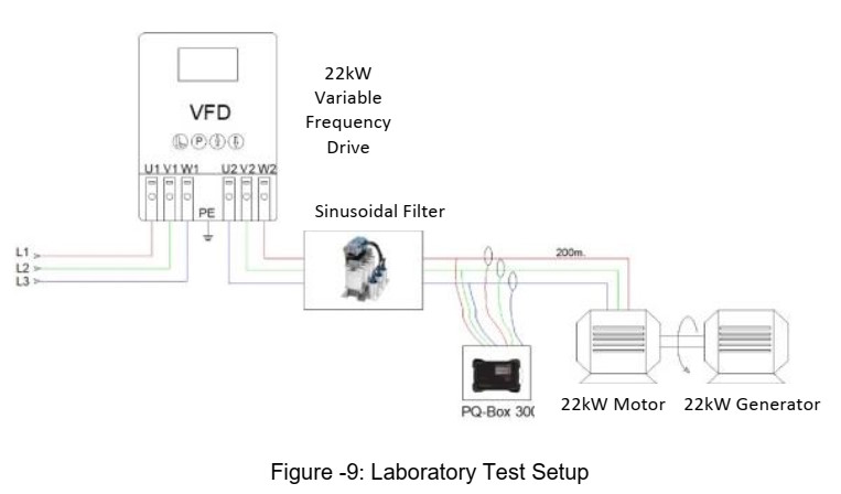
Figure 9 displays the configuration of the second test. In this setup, a 22kW variable frequency drive operating at 400V was linked to a 22kW asynchronous motor via a sinusoidal filter. The sine wave’s waveform was observed using an A-class measuring device. The cable utilized in this setup is 200 meters long and has a cross section of 3x1x6 mm2.
Test 1 : Starting a 22kW,400V, 50Hz Asynchronous Motor with a VFD
A variable speed drive with three-phase, 22kW, 400V, operating at a frequency of 50Hz and utilizing a 6-pulse diode input stage coupled with a PWM inverter stage has been supplied. An asynchronous motor rated at 22kW and designed for use with a nominal voltage of 400V has been linked to the variable speed drive using an unscreened cable with a cross-section of 3x1x6 mm² and a length of 200 m.
During the evaluation, the Total Harmonic Distortion of network voltage was recorded as 2%, while the voltage imbalance between phases was measured as 1%.
The test setup is illustrated in Figure-5.
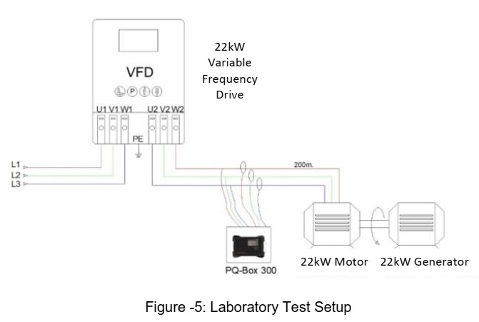
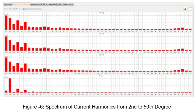
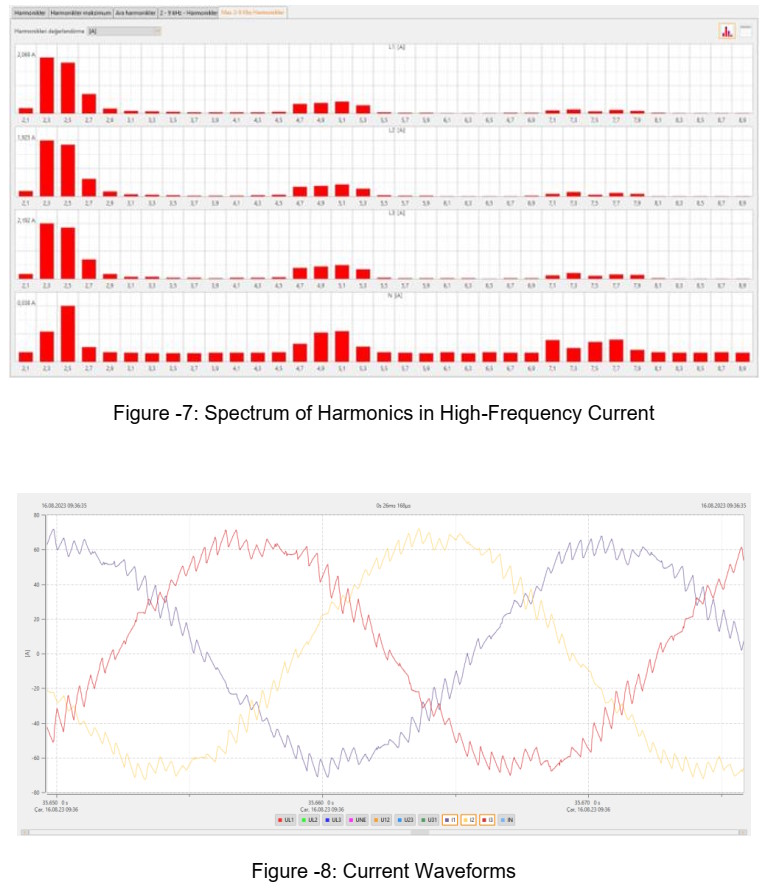
The test values were measured using the A class Measurement Device while the motor ran at a distance of 200m with a variable frequency drive. However, due to startup struggles and excessive noise and heating, the test was limited to 60 seconds. During this time, it was observed that the coupling mechanism opened due to vibration. The measurement results for this period are recorded in Figure-6, Figure-7, and Figure-8.
Test 2 : Starting a 22kW,400V, 50Hz Asynchronous Motor with a Sinusoidal Filter
A variable frequency drive with a 22kW, 400V, and 50Hz three-phase supply is provided. It includes a PWM converter stage with a six-pulse diode input stage. A sinusoidal filter rated at 22kW is connected to the output of the variable frequency drive.
An asynchronous motor rated at 22kW and designed for a nominal voltage level of 400V has been supplied. The motor is connected to the sinusoidal filter using a unscreened cable with a cross-section of 3x1x6 mm² and a length of 200 m. It operates on power from a grid voltage of 400V. Measurements have been taken over a period of 3 minutes.
The test setup is illustrated in Figure-9.
The test values were measured using the A class Measurement.
During the evaluation, the Total Harmonic Distortion of network voltage was recorded as 2%, while the voltage imbalance between phases was measured as 1%.
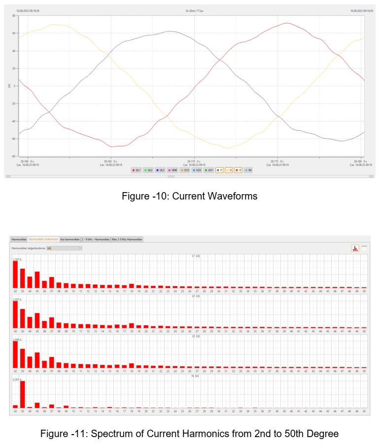
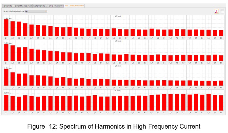
The measurement results are recorded in Figure-10, Figure-11, and Figure-12.
Test Results :
During the initial test, a 22kW asynchronous motor was powered by a variable frequency drive operating at a switching frequency of 6kHz. This setup involved supplying power from a distance of 200m via unscreened cable. However, the motor encountered difficulties during start-up, emitted noticeable noise, rapidly increased in temperature, and consequently the test had to be limited to only 60 seconds. Upon later inspection of the test setup, it became apparent that the motor-generator coupling mechanism had opened due to vibration.
Subsequently, a sinusoidal filter was connected to the output of the variable frequency drive before reapplying power to the motor. This time around there were no issues experienced as in previous tests and measurements were taken for 3 minutes before concluding this successful trial run. It was determined that with use of this sinusoidal filter on its output current waveform corrected itself back into pure sinusoidal form which differed from measured results obtained in earlier tests involving deviations off such shapes arising without its implementation; additionally both motor noise levels and temperatures decreased significantly
FINAL OUTCOME
A 22kW variable frequency drive operating at 400V and 50Hz, with a switching frequency of 6kHz, was utilized to test an asynchronous motor also rated at 22kW, 400V, and 50Hz. The tests included running the system both with and without a sinusoidal filter. The results section indicated that the output waveform with the sinusoidal filter closely resembled a true sinusoidal waveform. Furthermore, significant reductions in high differential mode voltages and common mode currents were observed. When using an unscreened cable, it became possible to control the speed of the asynchronous motor from a distance of up to 200m. Additionally, noise and heating levels from the motor decreased as well as ensuring reduced wear on insulation which will consequently extend its lifespan while reducing maintenance needs such as frequent bearing replacement.
REFERENCES
[1] Prof. Dr. R. Nejat Tunçay, Prof Dr. Emin Tacer., “Lecture notes on Power Electronics Circuits from the Faculty of Electrical and Electronics at Istanbul Technical University
[2] Ergun Elektrik, Product Catalogue, https://ergunelektrik.com/wpcontent/uploads/2023/04/ergun-elektrik-katalog_EN_2023-min.pdf
[3] J.M.Erdman, R.J. Kerkman, D.W. Schlegeland G.L. Skibinski, “Effect of PWM inverters on AC motor bearingcurrentsandshaftvoltages” IEEE Trans. On Ind. Applicats, vol. 32 pp. 250-259, March /April 1196
Didem Ergun Sezer
Elektrik Mühendisi
Ergun Elektrik A.Ş. İzmir
didem@ergunelektrik.com