
POWER FACTOR CORRECTION IN HARMONIC ENVIRONMENTS
As per network regulations, we use reactive power capacitor banks in our electrical facilities to improve power quality. However, the presence of harmonic currents in the system can lead to negative effects, such as capacitor failures and tripping of the main switches within the capacitor banks. It is crucial to comprehend the nature of harmonic currents and their impact on capacitors relies on fundamental electrical principles.
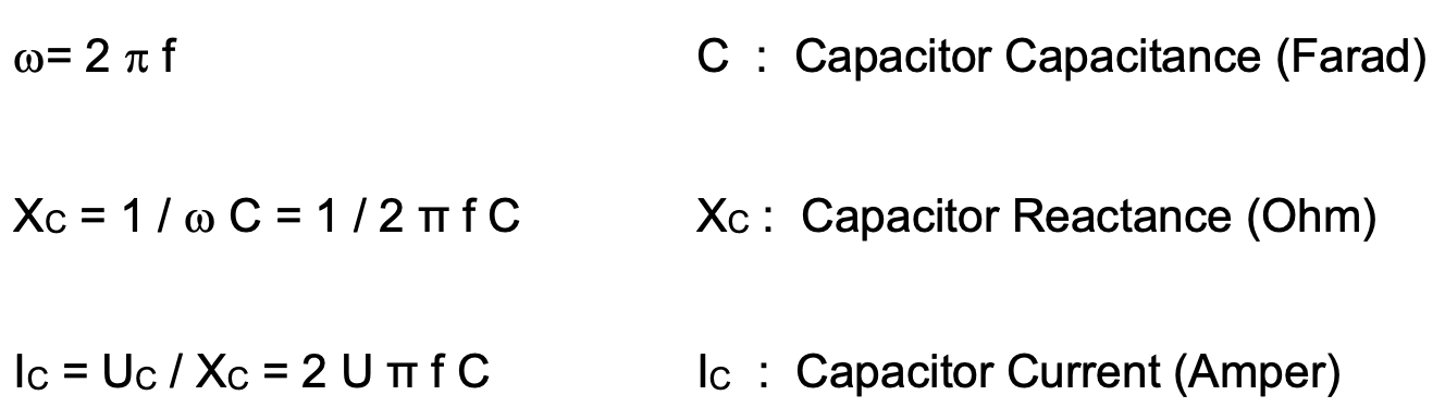
The formula indicates that capacitor current is directly proportional to frequency. This implies that if the applied voltage contains higher frequency components (harmonics) along with the fundamental frequency, the current flowing through the capacitor will increase in line with the harmonic frequency. Consequently, even a seemingly minor voltage component of a higher harmonic can generate a significantly larger current than what would be produced by the fundamental frequency voltage alone. As a result, this leads to a notable rise in the current flowing through the capacitor, which may exceed its safe operating limits.
Total Effective Current : I = √ (I12 + I32+ I52 + I72+ ……. + Ih2)
The IEC 60831 standard specifies that the maximum safe continuous current for capacitors at 1.3 times their rated current (1.3In). However, in electrical systems with harmonics, the currents flowing through the capacitors are much higher than this value. Consequently, capacitors lose their capacitance values in a very short time. Regardless of the brand, quality or voltage level, the facility will have to constantly supply and replace capacitors.
Another equally important issue is the occurrence of system resonances, which can be more inconvenient for a plant than the loss of capacitance by a capacitor.
RESONANCE
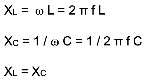
Our plant contains inductive loads such as transformers and motors, which exhibit an inductive reactance (XL) dependent on the mains frequency. Additionally, our power factor correction system includes capacitors with capacitive reactance (XC), both (XL&XC ) of which are expressed as functions of frequency. These reactive elements form a continuous oscillatory circuit that determines the overall resonant frequency of the system. Simultaneously, if non-linear loads cause harmonics in our plant, these harmonics will be multiples of the fundamental frequency – for instance, the 5th harmonic is at 250 Hz and the 7th harmonic is at 350 Hz.
When the frequencies of these vibration circuits formed by the reactances align with the harmonic frequency values, the possibility of resonance is very high. In cases of resonance, the system impedance reaches its minimum or maximum value. The minimum value is defined as series resonance and the maximum is defined as parallel resonance. This phenomenon can best explained with the basic electrical theory.
Let’s consider an industrial plant as an example:
When nonlinear loads are connected, parallel resonance into play.
The harmonics generated by the load are represented as a current source, with the power factor correction system and linear loads forming the parallel branches. If resonance occurs at any harmonic value between the capacitor of the power factor correction system and the entire grid, the total impedance becomes extremely large.
Since it is a current-sourced circuit, the harmonic voltage Vh = Zeq . Ih≈ ∞ leads to damage to either the power factor correction system or transformer.
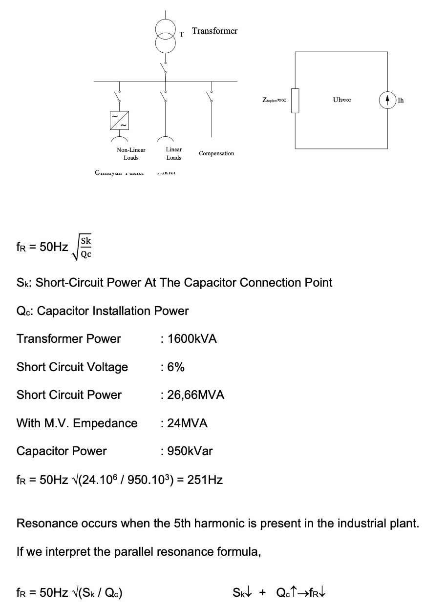
In our country, given the low network short-circuit powers and the high compensation power in the circuit to achieve a cosφ value of 0,98 due to our electricity tariff, facilities containing harmonic frequencies inevitably experience resonances.
During resonance with capacitors directly connected to the system, there is only a slight increase in grid voltage but a significant increase in capacitor current
Here are some examples of the following values:
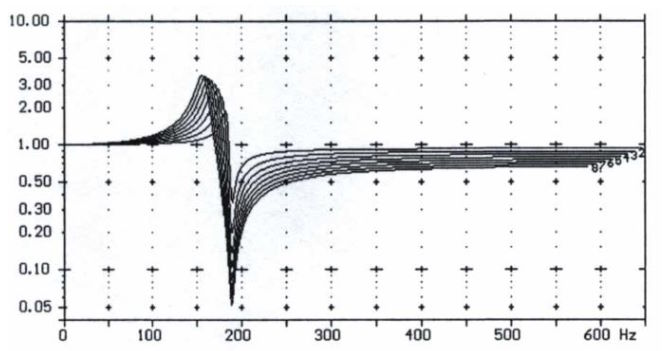
If resonance occurs at 250Hz,
- The rms value of the grid voltage increases by 1%.
- The peak value of the grid voltage increases by 10-15%.
- The rms value of the capacitor current increases by 25%.
If the resonance occurs at 550Hz,
- The rms value of the grid voltage increases by 0.5%
- The peak value of the grid voltage increases by 6-10%
- The rms value of the capacitor current increases by 50%
Capacitors in power factor correction systems without reactors will be loaded with currents that they cannot withstand, as shown by these examples.
HARMONIC INCREASE WITH HARMONICS
Even in the absence of resonance in the system, connecting capacitors without a reactor can amplify the existing harmonic distortion ratio as long as they are part of the circuit.
For instance,
If the system’s resonance frequency is within ±10% of the harmonic frequencies, they have the potential to cause up to a fourfold increase in harmonics depending on grid quality.
As capacitor stages are energized, there is an increase in harmonic voltage:
This is why two measurements are taken when examining a system: one with compensation in the circuit and one with compensation outside the circuit. The ratio by which capacitors increase the harmonics in the system is also determined.
As harmonics increase, so do their effects on the system, leading to an increase in errors in sensitive electronic device operations.
RESONANCES PREVENTION
As mentioned above, when harmonics are present in the grid, the power factor correction system appears capacitive to the grid. This causes harmonics to be multiplied and leads to resonance events. What we need is the power factor correction system to be capacitive at the nominal frequency of 50Hz for performing compensation, but to be inductive to the grid at harmonics in order to prevent resonance from occurring.

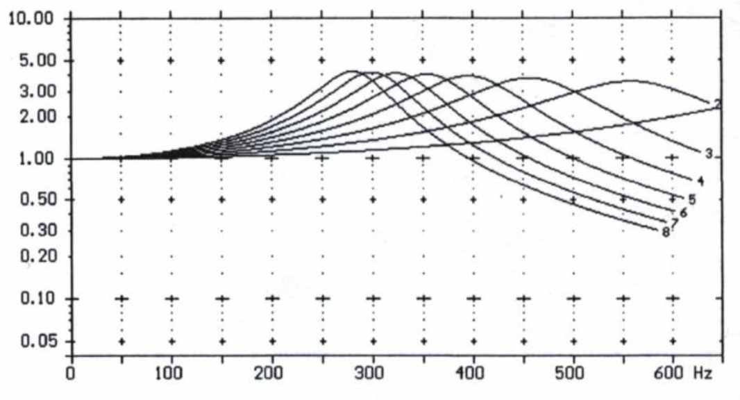
A reactor factor has been defined for the selection of a reactor and two values have been chosed.
A standard reactor factor of 7% at 189 Hz or 14% at 134 Hz is chosen for this purpose. The objective is to target the value just below the 5th and 3rd harmonics, which are commonly found in systems.
For instance, in a power factor correction system with a detuned reactor factor of 7%, the resonance frequency will drop below 250Hz, preventing all resonances at frequencies above the reactor frequency.
The graph below illustrates how detuned reactors in the power factor correction system reduce harmonic voltages.
The most crucial consideration in this system is to calculate the voltage on the capacitor terminals using the following formula after mounting the harmonic filter reactor. The capacitor voltage increases based on the reactor factor, meaning that 400V capacitors cannot be used in any system with a detuned reactor.
Uc = Un / (1-p)
Uc = Capacitor Voltage
Un = Nominal Voltage
The nominal operating voltage for a 24-hour period should be considered, rather than the permissible voltage rise values specified in the IEC60831 standard.
For a detuned circuit with a reactor factor of p = 7 and a 400V system, the nominal voltage of the capacitor should be 480V to accommodate ±10% voltage change tolerance.
In the case of a detuned circuit with a reactor factor of p = 14 and also operating at 400V, the nominal voltage of the capacitor should be adjusted to 525V considering ±10% voltage change tolerance.
Given that capacitors will operate above grid voltage level, it is important to account for lower active power readings on meters. The focus should then shift towards considering its impact on the 400V busbar instead of installed compensation power.
For example;
A capacitor bank installed with capacitors operating at 189Hz and 480V, with a reactor factor of p=7%, has a reactive power of 750kVAr.
In summary, using a detuned capacitor bank offers the following benefits:
- • Elimination of resonances
- Prevention of increased harmonic currents
- Prevention of capacitor and contactor failures, extending their lifespan and reducing maintenance costs
- Prevention of unwanted production outages caused by unnecessary opening of the main distribution panel’s input switch
- Reduction in unpredictable maintenance and repair costs
- Prevention of unaccountable energy losses and excessive load increases
- Approachment between cosφ and power factor
Didem Ergun Sezer
Ergun Elektrik A.Ş.
didem@ergunelektrik.com