
Capacitors are unquestionably one of the most essential passive components in the electrical grid. They are extensively deployed in industrial settings due to the requirements of electricity pricing structures. Unfortunately, it is concerning to observe that capacitors, despite the initial investment and installation, often experience a decline in their capacitance values, necessitating replacement within the facilities where they are utilized. Capacitors are indeed products that have the potential to provide extended service life. Nonetheless, regardless of their quality, improper usage can diminish the lifespan of capacitors. So, what factors influence the “Capacitor Service Life”?
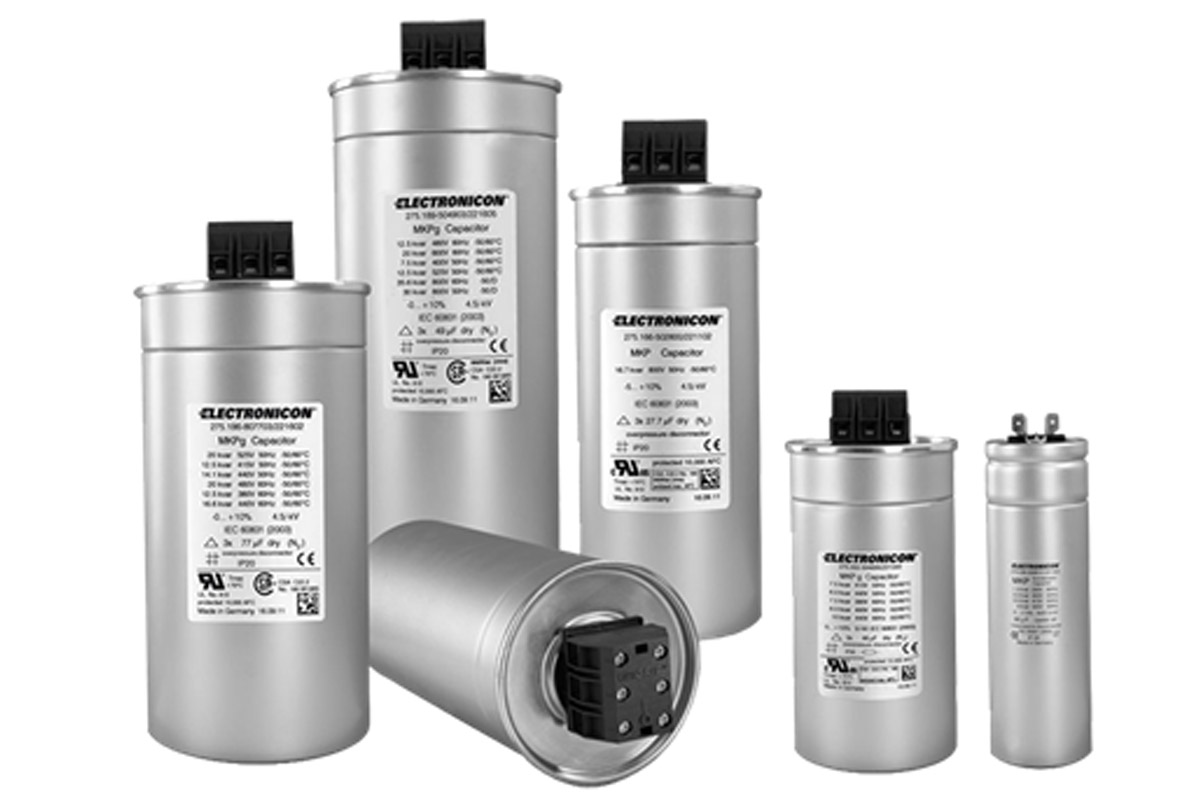
Electronicon GmbH Capacitors
Factors Affecting the Service Life of Capacitors
The service life of capacitors is influenced by numerous factors that directly impact their performance and durability. The key parameters governing a capacitor’s service life are as follows:
- Manufacturing Quality
- Safe Operation
- Voltage Withstand Capability
- Current Withstand Capacity
- Ambient Temperature
- Installation Errors
- Maintenance Errors
THE CAPACITOR MANUFACTURING QUALITY
The capacitor must be manufactured in accordance with the IEC 60831 standard. This compliance should be clearly indicated on the capacitor label. Furthermore, the label should specify the nominal voltage level of the capacitor at 50 Hz. When considering the application, the nominal voltage level at the network frequency provided on the capacitor label should be taken into account. The high-quality manufacturing of the capacitor results in a longer service life, better performance, and fewer failures.
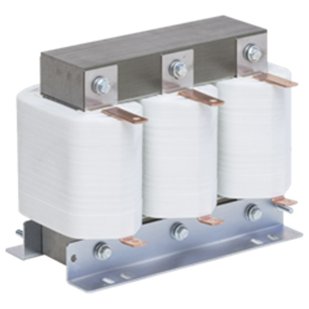
MKPg Technology
Capacitors fabricated using MKPg technology are produced from pure polypropylene film with a low-loss dielectric. One side of the polypropylene film is metallized with a zinc-aluminum vapor mixture under vacuum conditions. This manufacturing approach ensures the extended durability of the capacitor. The metallized polypropylene film is then wound, placed within aluminum housing cans, and the terminal connections are configured in a triangular arrangement. Subsequently, the cans are impregnated with N2 gas. The gas safeguards the windings from environmental influences. This gas is non-hazardous and permits the capacitor to be mounted in any orientation (horizontal or vertical).
Self-Healing Dielectric
When the electric field at a specific location on the capacitor exceeds the dielectric strength of the polypropylene film, such as during overvoltage switching events, the insulation breaks down and a sudden arc is formed. The heat generated by this arc causes the surrounding metallization to melt, promptly isolating that point. As a result, the capacitor does not short-circuit and can continue operating with minimal power loss. However, as these microscopic breakdown points accumulate over time, the capacitor’s service life is gradually diminished. The self-healing characteristic of capacitors ensures that the automatically isolated regions help sustain the device’s functionality.
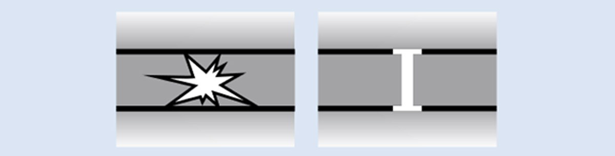
Self-healing Breakdown
SAFE OPERATION
Capacitors within energy systems are equipped with a variety of safety mechanisms that promote reliability and durability. These safeguards help mitigate potential malfunctions and risks while also streamlining maintenance procedures. Two essential safety features employed in capacitors are the Mechanical Fuse and Capacitor Terminals, which are engineered to ensure both mechanical and electrical safety of the system. Additional detailed information regarding the operation and significance of these safety mechanisms, such as mechanical fuses and capacitor terminals, is provided below.
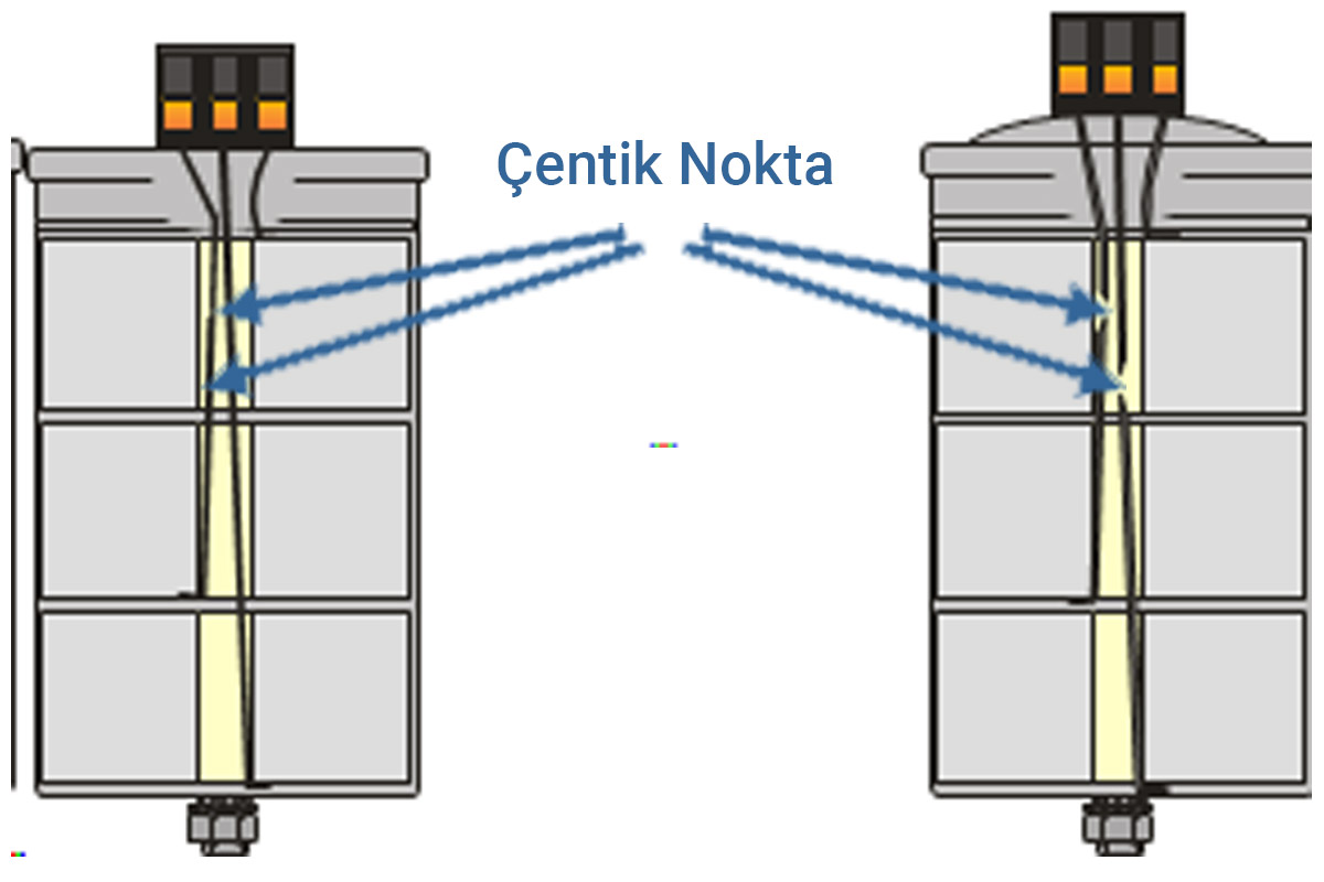
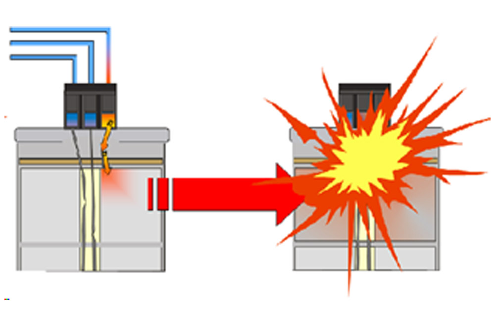
Break Action Mechanism
The increase in self-healing breakdowns within the capacitor results in a rise in internal pressure. To mitigate the risk of the capacitor exploding, a break action mechanism is implemented. This mechanism can be summarized as follows: The windings inside the capacitor are soldered in a triangular configuration. At the midpoint of the connecting wires, a weakened point in the form of a notch is present. As the pressure increases, the bellows rise upward, causing the connecting wire to break at this notch point, thereby interrupting the current path. The bellows located on the top of the capacitor’s outer aluminum casing then open, allowing the aluminum body to expand and preventing the capacitor from exploding and potentially causing a fire. An electrical maintenance technician can easily identify a faulty capacitor through visual inspection, as a capacitor that has reached the end of its service life will appear longer than the others.
However, it is important to note that this safety system can only function properly within the specified load and overload limits.
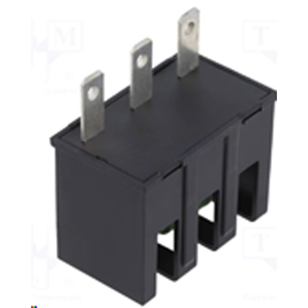
Capacitor Terminals
Aluminum-bodied capacitors must be grounded from the bottom stud. The capacitor terminals must meet IP20 protection class requirements and should be designed to prevent inadvertent human contact.

VOLTAGE WITHSTAND CAPABILITY
Excessive voltages may cause overheating of the polypropylene film, leading to a shorter lifespan for the capacitor. For a specific application, the capacitor’s label should indicate the appropriate nominal voltage level at the grid frequency. During continuous operation, the maximum allowable effective value of the sinusoidal AC voltage must not surpass the nominal voltage values provided in the capacitor’s data sheets. In accordance with the IEC 60831 standard, the capacitor should sustain the nominal voltage level continuously for 24 hours per day, and the daily overvoltage endurance values specified in the accompanying table should serve as a reference for applications.
| Nominal Capacitor Voltage | 400 V | 440 V | 480 V | 525 V | 690 V |
| 24 hours/day | 400 V | 440 V | 480 V | 525 V | 690 V |
| 8 hours/day | 440 V | 484 V | 528 V | 578 V | 759 V |
| 30 minutes/day | 460 V | 506 V | 552 V | 604 V | 793 V |
| 56 minutes/day | 480 V | 528 V | 576 V | 630 V | 828 V |
| 1 minute/day | 520 V | 572 V | 624 V | 683 V | 897 V |
This table is sourced from Electronicon GmbH product catalogue.
Detuned reactors connected in series with the capacitor will elevate the voltage at the capacitor terminals beyond the nominal grid voltage level. The voltage value specified in the formula will manifest at the capacitor terminal. Capacitors utilized with detuned reactors possess voltage ratings exceeding the grid voltage; consequently, capacitors matched to the grid voltage cannot be employed. As a result, capacitors paired with reactors must have a higher voltage rating than the grid voltage to prevent shortage in service life.
The voltage across a detuned reactor-equipped capacitor can be calculated as follows:
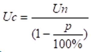
Un = Nominal Grid Voltage
Uc = Capacitor Voltage
P = Detuning Degree
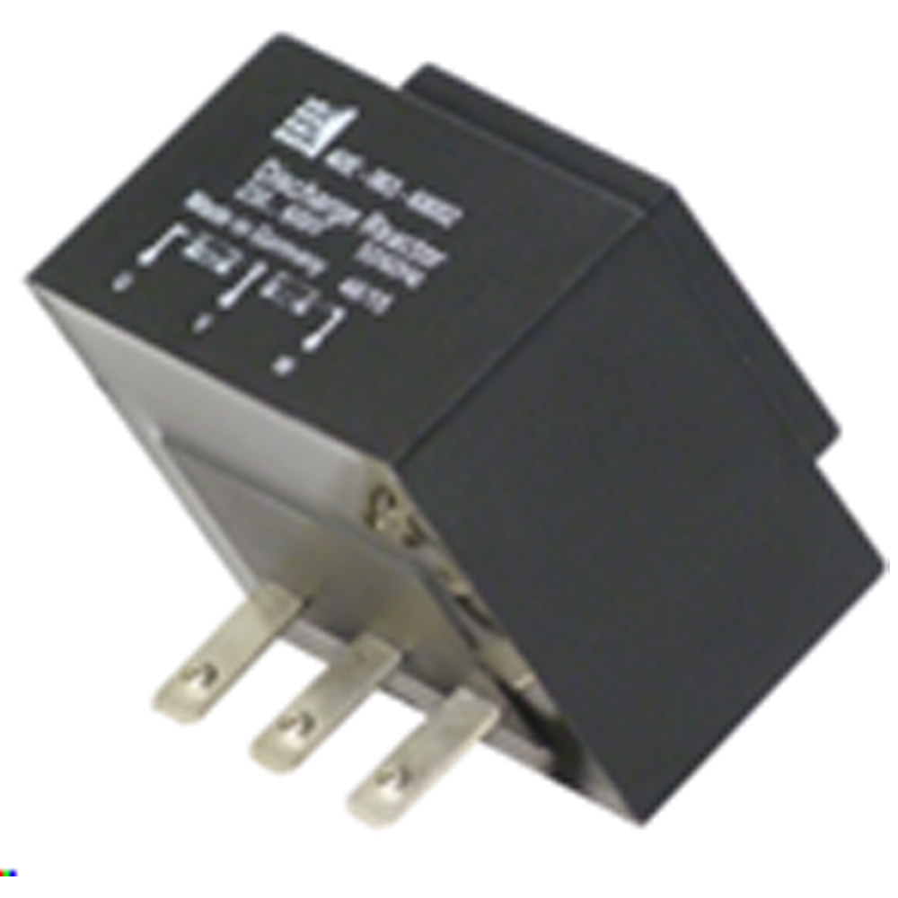
Capacitor Resistor Modules
When the contactor is opened and the capacitor is disconnected from the circuit, the residual voltage across the capacitor terminals must drop below 50 V within 60 seconds. During this discharge process, the temperature rise in the resistors should not exceed 70 °C per watt. Exceeding this limit would allow heat to be conducted to the capacitor windings, potentially leading to capacitor failure. When installing capacitors, the resistance values specified in the manufacturer’s technical documentation must be followed.
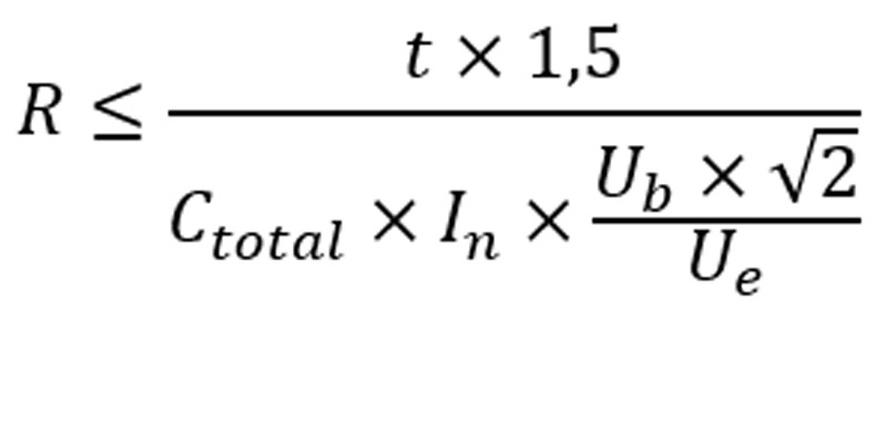
Discharge resistors can also be calculated using the formula below.
t = Discharge Period (sn)
CT = Capacitance Value of a Single Phase
Ctotal = Total Capacitance Value
Ub = Operating Voltage
R = Resistance Value of the Discharge Module
Ue = Maximum Allowed Voltage After a Specified Time Period T
For single phase capacitor

For three phase capacitor
Manual Operation
In capacitor bank installations, it is a common practice to install manual control buttons adjacent to the reactive power controller. This approach is designed and essential for intervening in the event of a reactive power controller malfunction. However, this practice is not strictly necessary and is not recommended. In reality, every facility should maintain a spare reactive power controller with identical technical specifications in case the primary controller fails.
The limitations of manual operation can be summarized as follows: When the contactor is opened or the capacitor is disconnected from the circuit, a residual voltage remains that depends on the point in the sinusoidal waveform where the circuit was interrupted. The capacitor must be discharged to approximately 5-10% of its nominal voltage level before it can be re-energized.
The discharge time of a capacitor is specified by the manufacturer of the reactive power controller, but this time is not factored into manual hand control operations. When capacitors are switched manually, the voltage at the moment of switching may coincide with the residual voltage across the capacitor terminals, leading to overheating of the capacitor’s polypropylene film and potential damage.
I f the capacitor’s energization and de-energization durations in the system are less than 8 seconds due to operational constraints, it is recommended to install discharge reactors in addition to discharge resistors on the capacitor.
CURRENT WITHSTAND CAPACITY
The ability to withstand current surges is a critical factor for the safety and longevity of components used in electrical systems. Capacitors, especially those employed in power factor correction, can be exposed to both short-term and long-term overcurrents. Short-term overcurrents are characterized by high discharge currents that occur during the switching of automatic capacitor steps, while long-term overcurrents arise from continuous current increases caused by harmonic effects. This is a crucial consideration that directly impacts the performance and durability of capacitors. Safeguarding capacitors against both temporary and persistent overcurrents is essential for the secure and efficient operation of electrical systems.
Short-Term Overcurrents
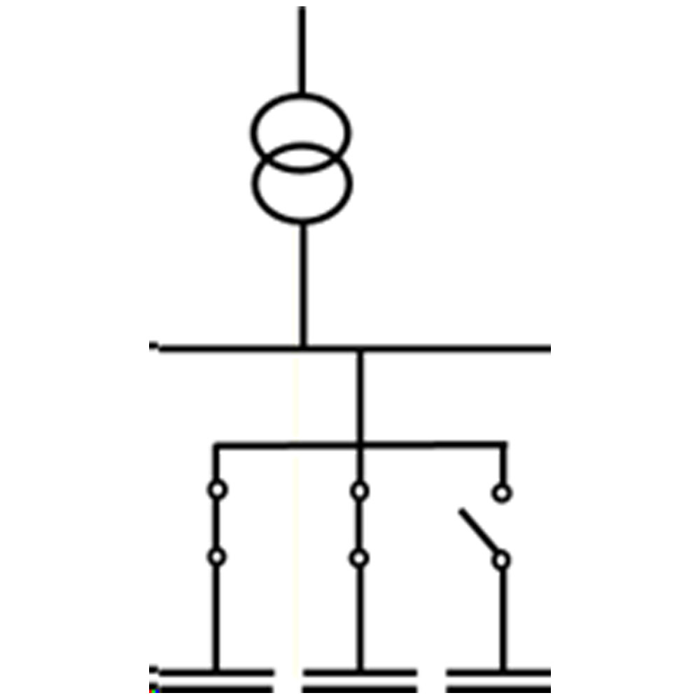
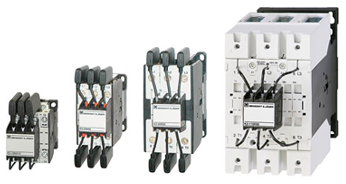
Switching of Automatic Capacitor Steps: In response to reactive power demands, contactors in capacitor banks manage the engagement and disengagement of capacitor stages. Switching capacitors can cause short-term resonances and potentially generate very high discharge currents. These currents are controlled by pre-closing resistors within the capacitor contactors.
By utilizing contactors with pre-make contacts, the switch-on current is reduced from 200 In to 70 In. These resistors help protect capacitors from short-term overcurrents. In accordance with the IEC 60947-4-1 standard, it is essential to use contactors equipped with pre-closing resistors for switching in power factor correction steps.
Long-Term Overcurrents Harmonics
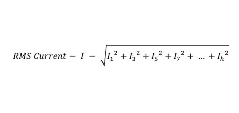
Harmonics are deviations from the ideal waveform of voltage and current, which occur at multiples of the fundamental frequency. These distortions are caused by the connection of nonlinear loads to the electrical energy system. The most prevalent harmonic values encountered in industry are the 5th, 7th, 11th, and 13th harmonics. In facilities experiencing harmonic issues, it is often necessary to replace capacitors and other related equipment.
This can be explained very simply by Ohm’s law.
C: Capacitor Capacity (Farad)
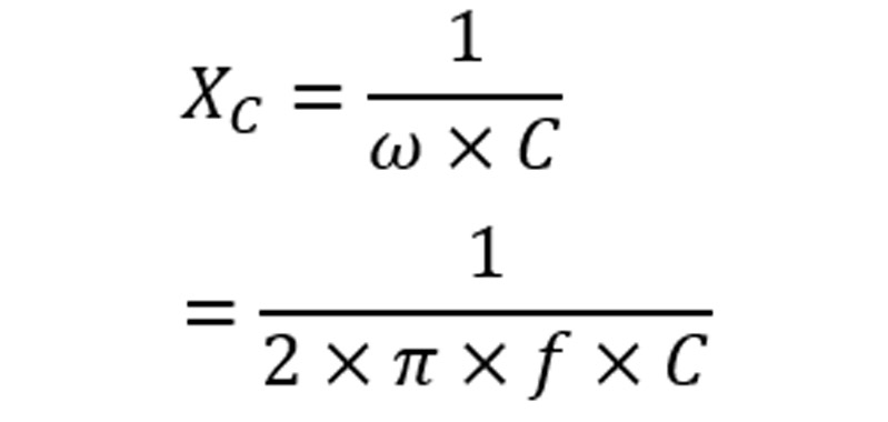
XC: Capacitor Reactance (Ohm)
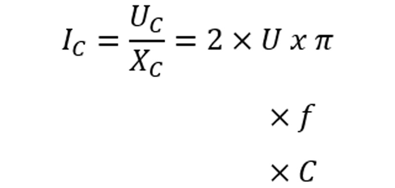
IC: Capacitor Current (Ampere)
As the formula indicates, current and frequency are directly proportional.
Given this direct proportionality and the fact that harmonic currents are integer multiples of the network frequency, an excessive amount of current will pass through the capacitor.
According to the EN 60831 standard, capacitors have a maximum continuous withstand current value of 1.3 times their rated current (1.3 In). However, in environments with harmonics, the currents flowing through the capacitors often exceed this limit. As a result, capacitors can experience rapid degradation in their capacitance and service life. Regardless of the brand, quality, or voltage rating, industrial facilities may need to continuously replace their capacitors. The only way to protect capacitors in an environment with harmonic currents is to install a harmonic filter (detuned) reactor in series with the capacitors.
AMBIENT TEMPERATURE
To optimize the service life of the capacitors, it is critical to adhere to all electrical and thermal specifications and instructions provided on their labels, data sheets, and catalogs. The achievable operating temperature is denoted by a letter, which defines the upper limit values of the temperature class. As per the IEC 60831 standard, the table below outlines the permissible maximum ambient temperatures for each temperature class of capacitors. The service life of the capacitor is assessed based on the service life values specified in the technical documents of the manufacturing companies, in accordance with the temperature class.
Service life of a 525 V MKPg type capacitor:
At temperature class D level > 150,000 hours
| Temperature Category | Ambient Temperature Limits | ||
| Maximum | Max. Average
24 Hours |
Max. Average
365 Days |
|
| B | 45 °C | 35 °C | 25 °C |
| C | 50 °C | 40 °C | 30 °C |
| D | 55 °C | 45 °C | 35 °C |
This table is sourced from Electronicon GmbH product catalogue.
7 °C RULE
An increase in temperature of 7 °C results in a 50% reduction in a capacitor’s service life. When a capacitor is placed in an excessively hot environment, its lifespan decreases in a logarithmic manner. Typically, a 7 °C rise in ambient temperature halves the capacitor’s lifespan.
As demonstrated, temperature has a significant effect on capacitor lifespan. To prevent excessive heating of capacitors, they must be situated away from external heat sources and allowed to cool freely. Capacitors should not be installed adjacent to or on top of heat-generating components such as reactors or busbars.
Installing a fan in the electrical panel can help expel the generated heat. Additionally, providing ventilation and/or cooling for the electrical rooms is necessary. The annual average temperature of the electrical room should not surpass 35 °C.
INSTALLATION ERRORS
Using a cable with a cross-section below the standard specification, employing the wrong cable terminal, or over-tightening terminal screws can cause the terminals to overheat. This excess heat then transfers into the capacitor, potentially damaging and resulting in a failure of the capacitor windings. It is critical to not exceed the permitted torque values for both terminal and mounting screws. (Designs K, L, M)
| DESIGN | 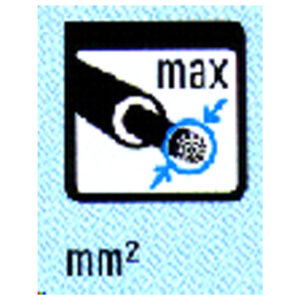 |
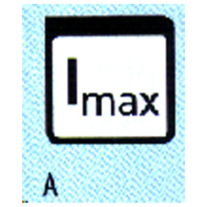 |
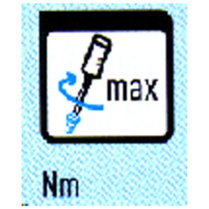 |
| mm2 | A | Nm | |
| A | 6 | 16 | – |
| K | 6* | 30 | 1,2……2,0 |
| 10** | |||
| L | 25* | 43 | 2,5……3,0 |
| M | 35* | 80 | 3,2……3,7 |
| 50** |
This table is sourced from Electronicon GmbH product catalogue.
*with cable strip | **without cable strip
If the terminal screws are not properly tightened, it may lead to overheating and operational issues within the terminal. In summary, the installation process should be carried out using a torque wrench to ensure appropriate tightening.
The EN 60831 standard stipulates the maximum continuous current rating for capacitors as 1.3 times the nominal current (1.3 In). This specification should be taken into account when choosing the power supply cable.
MAINTENANCE ERRORS
Maintaining capacitors regularly is essential for their efficient and reliable operation over an extended period. This maintenance extends the service life of the capacitor and the system, enhancing energy efficiency and minimizing the risk of failures. Additionally, a regular and careful maintenance program improves the reliability of capacitors and optimizes the overall performance of the power factor correction system. The listed capacitor maintenance steps make significant contributions to preventing failures and sustaining energy efficiency.
Regular Cleaning of Capacitor Terminals: Frequent cleaning of capacitor terminals is essential to prevent oxidation and the buildup of contaminants. Maintaining clean terminals enhances the quality of electrical connections and mitigates the risk of overheating.
Periodic Monitoring of Capacitor Current: Regularly measuring and comparing capacitor current to nominal values is crucial. The capacitor current should be within 15% of the nominal rating. If the current falls below 85% of the nominal value, the relevant stage must be deactivated, and the underperforming capacitors should be replaced. These inspections are essential for monitoring capacitor performance and identifying potential problems early on.
Examination of Connected Components: The condition of the contacts in the operational components linked to the capacitors should be evaluated. Worn or damaged contacts can diminish the system’s efficiency and lead to failures.
Visual Inspection for Physical Deterioration: Capacitors should undergo thorough visual inspections to detect any physical deterioration or damage. Capacitors exhibiting signs of swelling, leakage, or other mechanical issues should be immediately removed from service and replaced to maintain system reliability and performance.
Monitoring Temperature and Ventilation: Regularly assessing the temperature and ventilation of the capacitor environment is crucial for maintaining optimal operating conditions. Elevated temperatures can diminish the service life and performance of the capacitors.
If the capacitors exhibit sensitivity to the concepts discussed in this paper, they will achieve their full rated service life in a robust manner.
Didem Ergun Sezer
Electrical Engineer
Ergun Elektrik A.Ş.
didem@ergunelektrik.com