

CAPACITIVE CURRENT COMPENSATION WITH SHUNT REACTORS
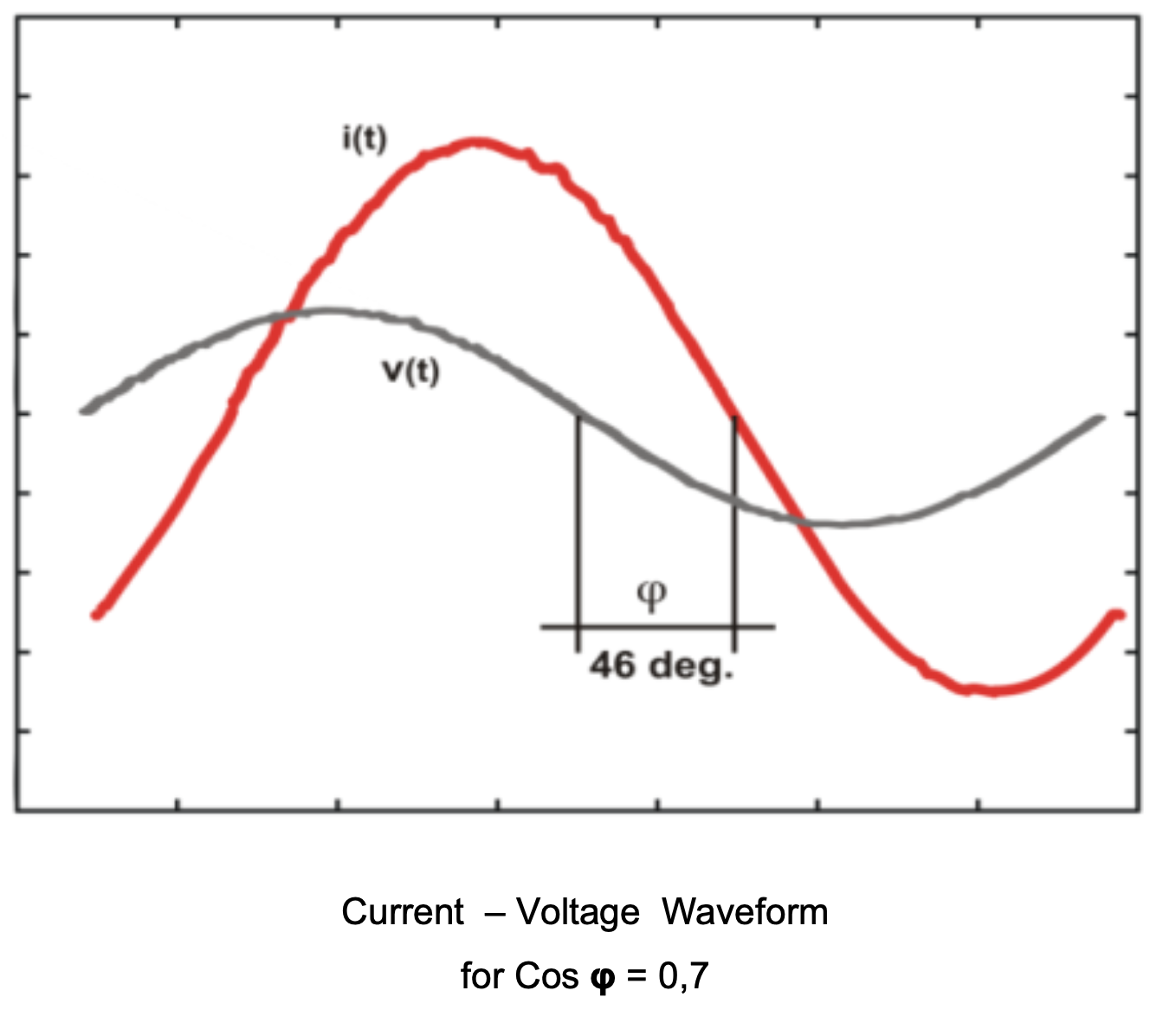
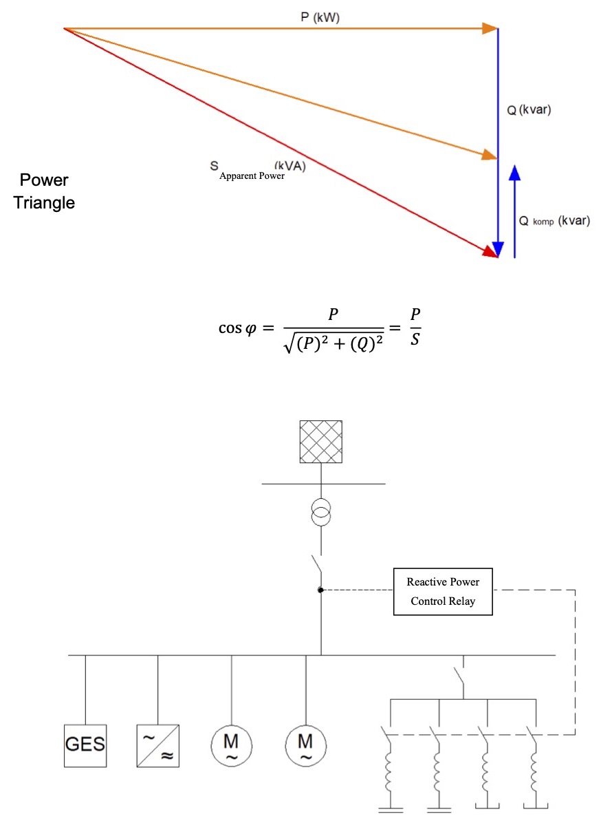
In Turkey, the acceptable ratio of “Reactive Inductive Energy / Active Energy” is 20%, while the ratio of “Reactive Capacitive Energy / Active Energy” is 15%. This requirement implies maintaining Cosφ in the range of 0.98 to 1 in the inductive region and Cosφ in the range of 0.99 to 1 in the capacitive region. To ensure compliance with these criteria, power measurement for determining facility needs must be conducted over a period of 24 hours, during which Cosφ value is measured as well. This value represents the phase shift between current and voltage waves, where active power and reactive power are perpendicular to each other while apparent power forms an angle φ with active power.
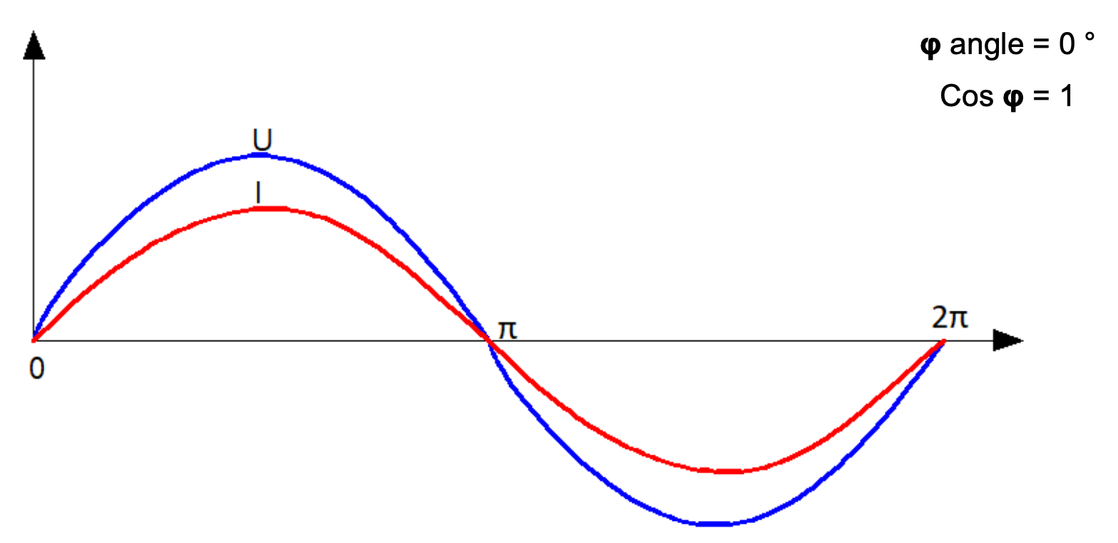
If the loads are drawing pure resistive current from the grid, such as electric heating resistors, and if there are no inductive or capacitive loads, the voltage and current are in phase.
If the installation is resistive in nature, there is no need to install a compensation system.
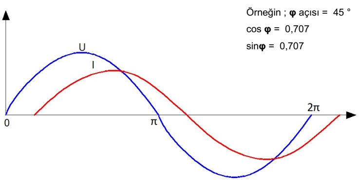
If the loads draw inductive current from the grid, such as motors, transformers, and lighting ballasts, the inductive reactive current lags 90° behind the voltage. In cases where the installation is inductive in nature, a capacitive compensation system should be installed. The compensation system must comprise stages with capacitors.
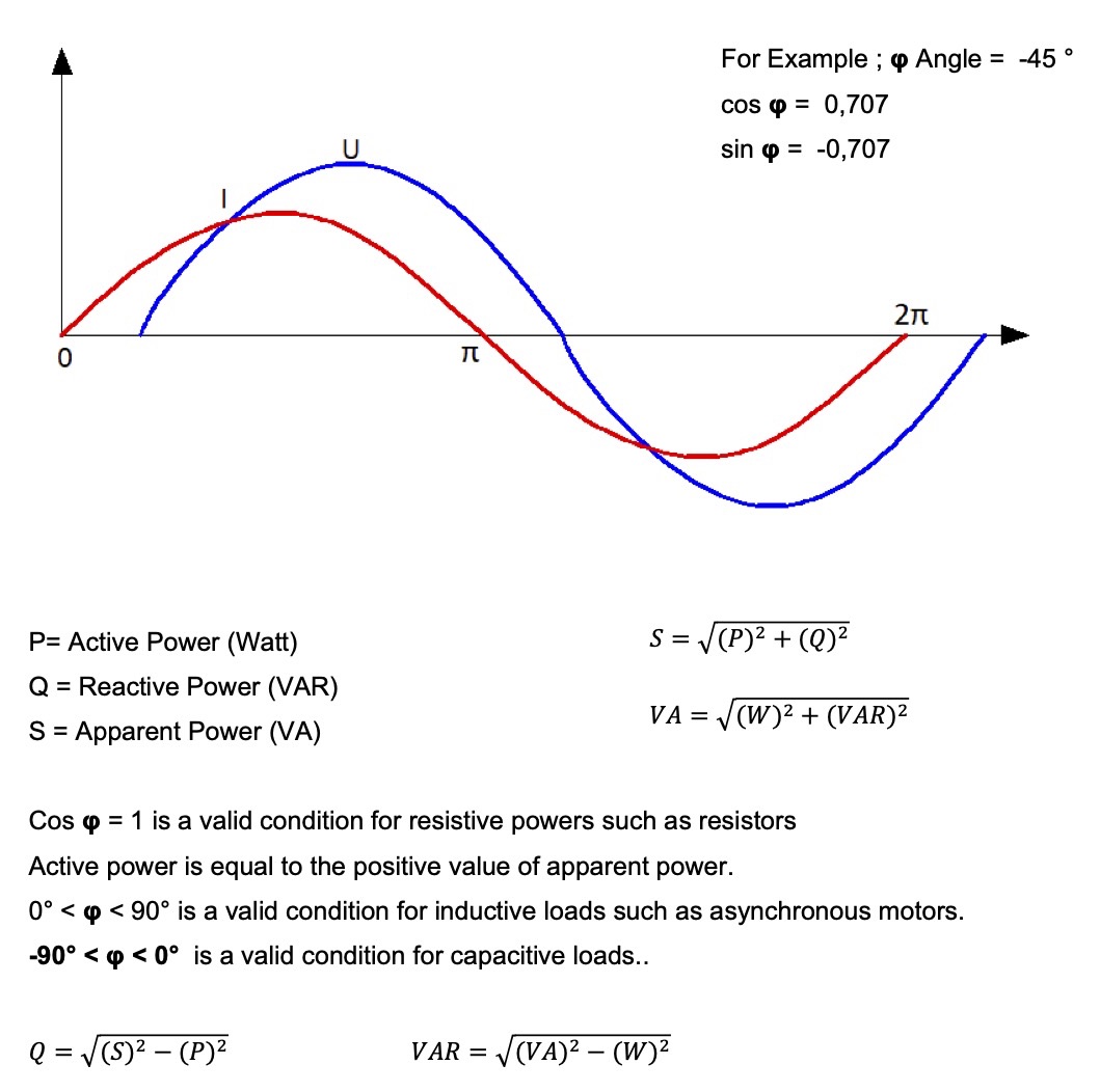
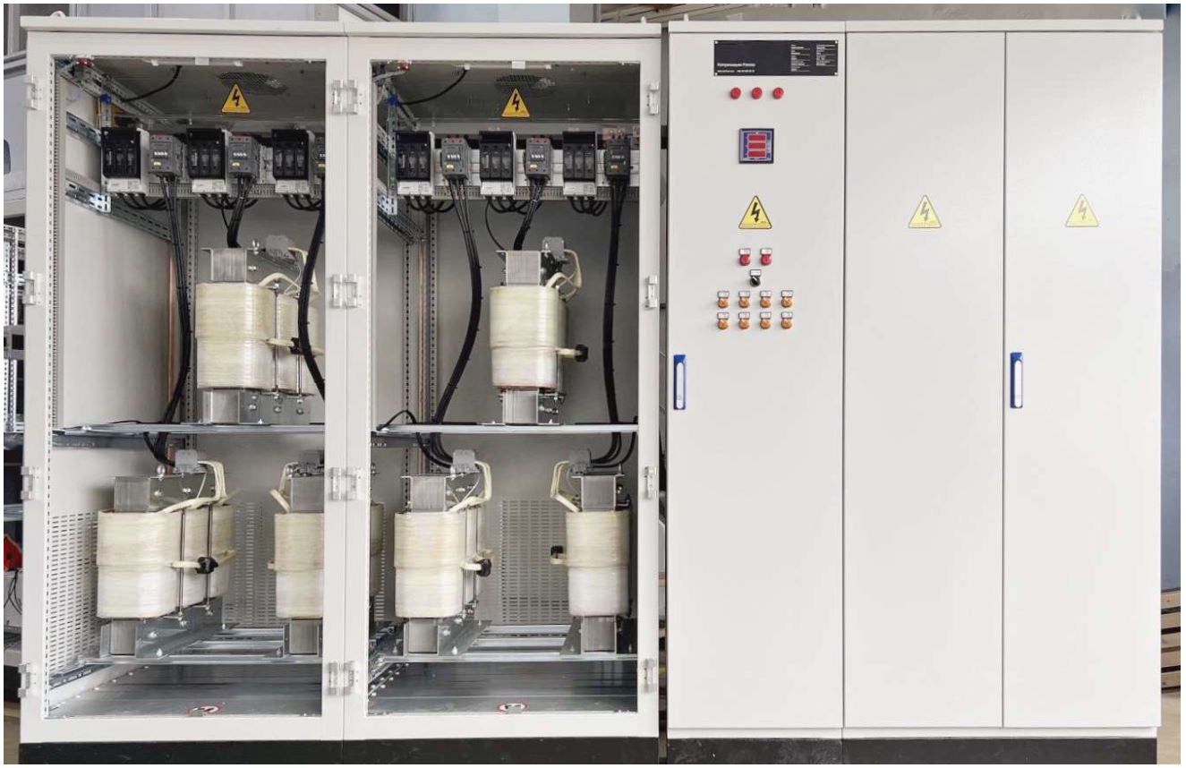
When loads draw capacitive current from the grid, like in installations with long underground cables, large uninterruptible power supplies, and solar power plants, the capacitive reactive current leads the voltage by 90°. If the installation is predominantly capacitive, it requires an inductive compensation system to be installed, consisting of stages with inductive load reactors.
If the facility being measured has an inductive reactive character, a capacitive compensation panel with stages of capacitors is installed

If the facility being measured has reactive capacitive characteristics, an inductive compensation panel is installed. This panel consists of stages of inductive reactors.
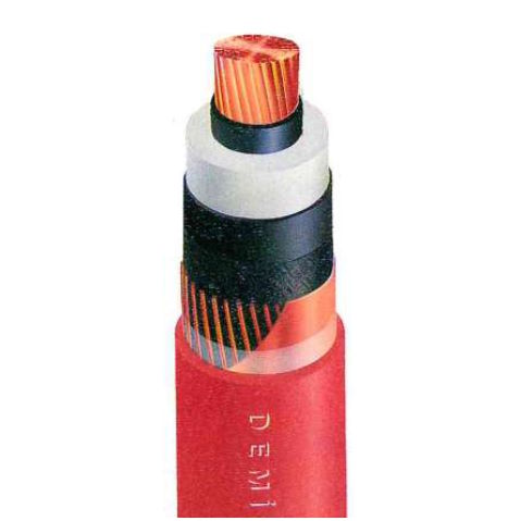
Medium-voltage cables have an insulation layer on the conductor core and a conductive screen on top of the insulation, creating a capacitive effect. The capacitance values for these cables can be found in their catalog data.
For instance, a 1 x 95/16 mm2 XLPE cable has a capacitance value of 0.15 μFarad/km When distances are in the kilometer range, significant capacitive load currents flow. These currents can be calculated from the catalog value. They benefit the grid because most loads are inductive, but if they flow through a meter circuit, it will accrue reactive energy charges. In such cases, an inductive compensation system with staged inductive load reactors must be installed.
Reactive power per meter can be calculated if the cable distance is known.
𝑄 = √3 x U x I 𝑐
Inductive load reactors are essentially pure inductive loads with a reactor factor of 100%. They are constructed by winding copper or aluminum around a ferromagnetic core. To ensure proper functionality, it is important that the ferromagnetic core does not exceed a certain value on the hysteresis curve at the saturation point.
Another application area involves addressing capacitive load flow to the grid caused by long overhead cables supplying Solar Energy Production Plants and their associated inverter devices. During daylight hours, motor loads connected to the plant fulfill capacitive compensation needs. However, during off-peak hours, when these loads are disconnected from the circuit, capacitive current flows into the grid due to both MV cables and inverter devices.
If this scenario occurs regularly every night, reactive energy costs will be reflected in electricity bills monthly. To address this issue efficiently throughout day and night periods,, installation of compensatory measures such as daytime capacitor banks for capacitive compensation stages and nighttime inclusion of inductive load reactors becomes imperative within an overall system solution framework.
The implemented stages within this comprehensive setup should be managed using a reactive power control relay capable of operation in both directions – activation and deactivation based on system requirements for effective overall compensation management strategy across varied time frames.
Measurements Conducted During Nighttime at a Solar Energy Facility
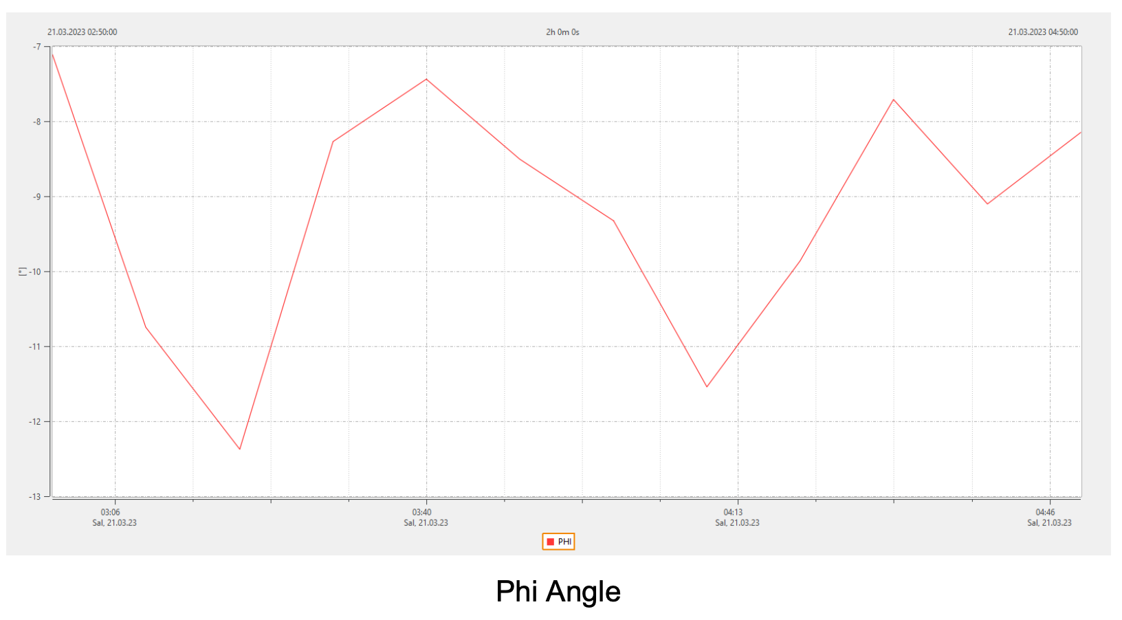
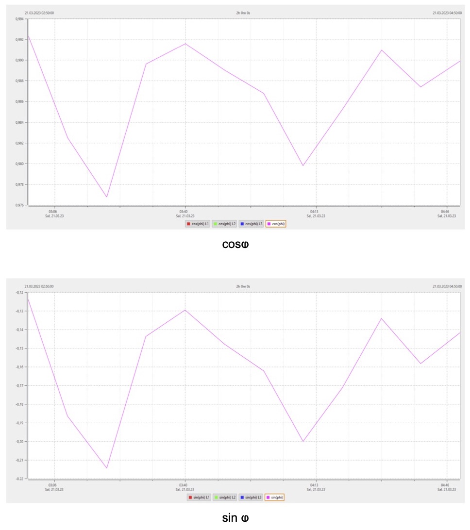
The above measurement results indicate that the reactive power requirement of a facility needs to be determined by conducting a 24-hour power measurement using a power measuring device. If necessary, inductive load reactors should then be installed in the compensation panel gradually.
Didem Ergun Sezer
Ergun Elektrik A.Ş.
didem@ergunelektrik.com