
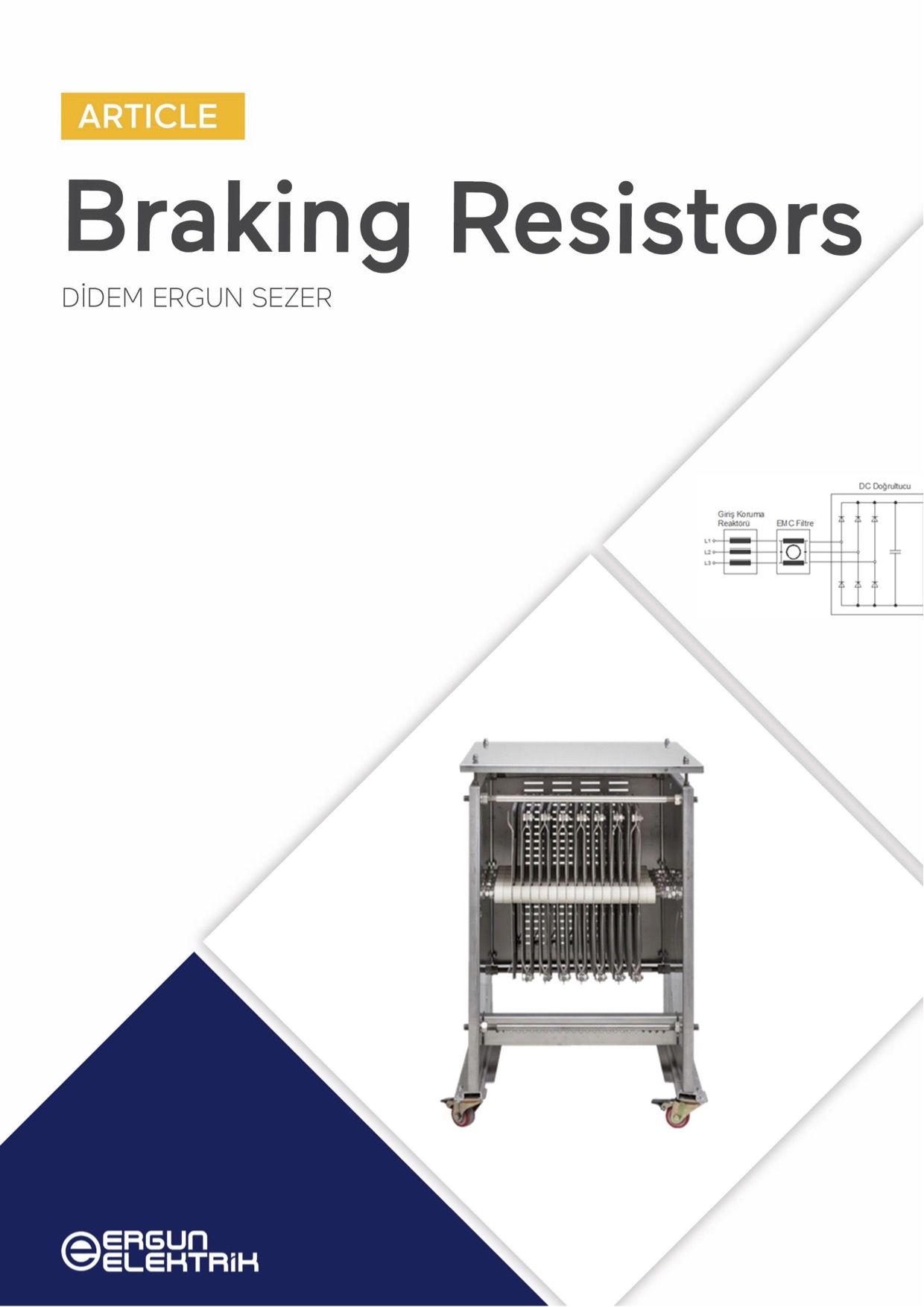
BRAKING RESISTORS
Variable frequency drives are commonly used to drive asynchronous motors in industrial applications. These drives, based on PWM inverters, offer high energy efficiency, precise movement control, high starting torque, and low starting current.
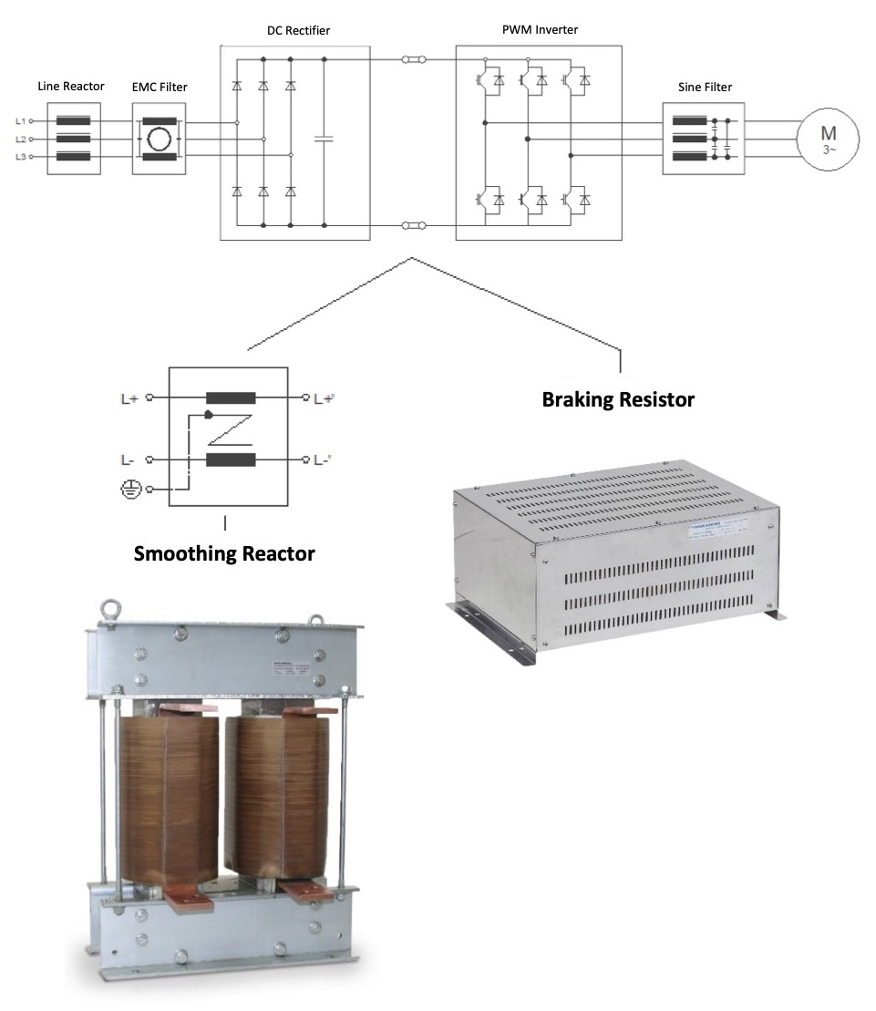
During the input stage of the variable frequency drive, the DC bus voltage is acquired using a 6-pulse diode rectifier circuit. The inverter circuit, which comprises semiconductor switches, operates based on pulse width modulation. These semiconductor switches are designed to switch at specific frequencies and pulse patterns in order to achieve the desired output voltage with the required magnitude and frequency. The PWM principle aims to generate a sinusoidal voltage at the fundamental frequency by maintaining a constant switching frequency while adjusting the width of the inverter output voltage pulses.

Variable frequency drives are also used in applications such as cranes, elevators, conveyor belts, and more. In these scenarios, when the speed reference of the variable frequency drive decreases, the motor enters the generator operating zone and performs a braking function. This causes an accumulation of energy in the DC bus that surpasses the rectifier circuit and is unable to flow back to the grid, resulting in a voltage rise. To address this issue, a resistor connected to the DC bus dissipates this excess energy by converting it into heat energy – essentially acting like a load (consumer).
If a braking resistor is not used, the DC bus voltage level of the frequency converter will keep rising until the protection devices of the variable frequency drive cut off the circuit.

The resistance value, or ohmic value, of the braking resistor should be chosen to balance the DC bus voltage with the braking current produced by the asynchronous motor.
Variable frequency drive manufacturers state the necessary resistance value, or ohmic value, to prevent DC bus voltage from rising during braking on the information pages of their products. The chosen resistor must align with this specified value.
Selecting the power of the braking resistor is crucial because it converts regenerative power into heat energy. The voltage and resistance values can be obtained from the variable frequency drive manufacturer’s information page.

The peak power, or maximum power value, is determined based on the braking power in common applications with a working cycle.
The selection of power is dependent on this working cycle and requires determination of the working time (period) and cycle time.
ED = Cycle Time
SD = Working Time (Period)

The duration for which the braking resistors are active can vary depending on the specific application in which they are used.
Braking resistors are primarily used in crane operations, where heavy-duty braking is required due to the vertical movement. The design of the braking resistor should include a plate and body that can effectively dissipate heat energy into the environment. Inadequate dissipation could lead to burn out when consecutive services are needed. Additionally, for bridge motors which are horizontally movable, the resistor design should be capable of stopping the mass at the desired point.
Ideal Type of Connection for Crane Applications:
Didem Ergun Sezer
Ergun Elektrik A.Ş.
didem@ergunelektrik.com