

APPLICATION OF 75KW SERIAL PASSIVE HARMONIC FILTER
SUMMARY
The use of power electronic-based drive systems in industry has increased over time, leading to a rise in the usage of non-linear loads. This widespread adoption has resulted in an increase in network harmonic pollution, particularly in specific industrial areas (background harmonic distortion). The variable frequency drive is currently the most commonly used power electronic device in industry, and while their individual powers are on the order of kilowatts, their cumulative impact on network harmonic distortion is significant due to the large number of units used. It is crucial to prevent the flow of current harmonics to the grid at each device’s input as this could lead to a substantial reduction in network harmonic distortion. To explore this further, a laboratory test was conducted using a widely utilized 3-phase 6-diode rectifier variable frequency drive with a power rating of 75 kW within an industrial setting. The device was installed and its effect on reducing harmonic currents flowing into the grid was measured using a serial passive harmonic filter.
INTRODUCTION
The most common application of driving asynchronous motors in the industry is with a variable frequency drive. Pulse Width Modulation (PWM) inverter-based variable frequency drives offer high energy efficiency, precise motion control, high starting torque, and low starting current, making them widely used. However, the 6-pulse diode rectifier circuit in the input stage of the drive can be considered a harmonic current source that generates and injects harmonics such as 5th, 7th, 11th,and 13th according to h = np ±1 formula.

Figure-1: Variable Frequency Drive Diagram
When each harmonic current passes through different impedances in accordance with Ohm’s Law, the equation 𝑈ℎ = 𝐼ℎ 𝑥 𝑍ℎ is met. This results in the generation of harmonic voltages that contribute to grid pollution, also recognized as grid harmonic voltage distortion (background harmonics).
The provided formula is shown below. [1]

THE DESIGN OF 75KW SERIAL PASSIVE FILTER
A 75 kW, 400V, 50Hz three-phase Serial Passive Filter incorporates three reactors and three capacitors. The high-impedance L1 reactor is connected in series while the lower-impedance L3 reactor is linked in parallel to the circuit. A capacitor is placed in series with the L3 reactor to construct the filter circuit. Both the inductance of the reactor and capacitance value of the capacitor are modified to mitigate a wide range of harmonics. An L2 reactor has been added to restrict harmonic currents on the load side.
Most of these harmonic currents generated by variable frequency drives travel through a circuit formed by the L3 reactor and capacitor.The function of this design serves as an isolation unit for harmonics between grid and variable frequency drive without reflecting any issues back onto other loads.
Grid problems do not affect it; instead, it mainly absorbs harmonic currents produced by variable frequency drives

Figure-2: Serial Passive Filter Diagram
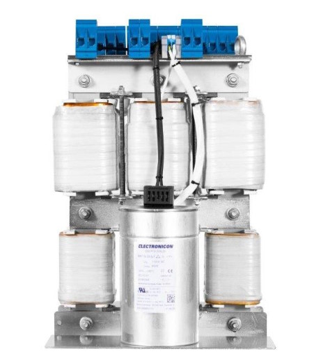
Figure-3: 75kW Serial Passive Harmonic Filter
TEST
In the laboratory, a test setup has been prepared consisting of a 3-phase 75 kW 400V, 50Hz variable frequency drive with a diode input stage. An asynchronous motor rated at 400V and 75 kW has been coupled to a generator of the same power using a coupling method to enable testing at full load. The measurement device installed for obtaining test results is of A class. Two installations have been conducted with the speed control device mentioned earlier.
In the first test, the direct connection of the 75 kW 400V variable frequency drive to the grid allowed for measuring current harmonic distortion ratio.
In the second test, a series passive filter was connected in front of this variable frequency drive powered from grid and its corresponding current harmonic distortion ratio was measured as well.
Testing 75KW Variable Frequency Drive:
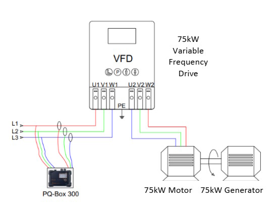
Figure-4: Laboratory Test Setup
A 75 kW 400V, 50Hz variable frequency drive has been operated at full load while connected directly to the grid. The current harmonic distortion ratio was measured, and the test setup can be seen in Figure-4.
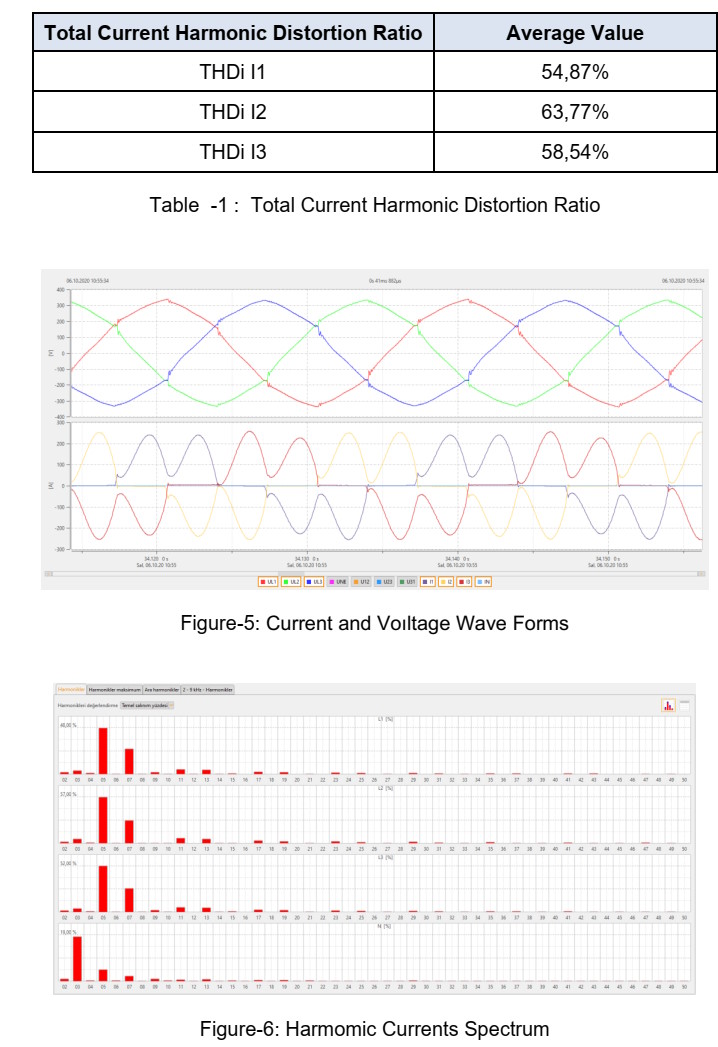
Measurement results are provided in Figure-5 and Figure-6.
During the test, the grid voltage harmonic distortion ratio was found to be THDu = 2%, with a voltage imbalance between phases of 1%.
Testing 75KW Variable Frequency Drive with Serial Passive Filter :
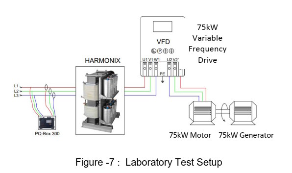
The variable frequency drive is connected to a serial passive filter and then to the grid. It has been operating at full load, with measurements taken for current harmonic distortion.
The test setup can be seen in Figure-7.
Throughout the test, the grid voltage was found to have a harmonic distortion rate of 2% and a voltage imbalance between phases of 1%.
Test Results :
Measurement tests were carried out with a network voltage harmonic distortion ratio of THDu = 2% and a voltage imbalance between phases of 1%. When testing a directfed variable frequency drive from the grid, it was noted that the total input current harmonic distortion ratio was 63.77%.
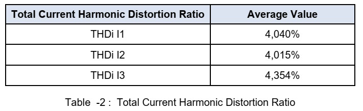
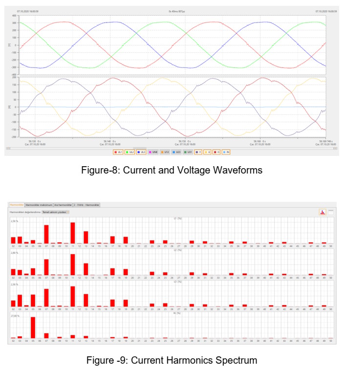
However, upon connecting a serial passive filter with a power of 75kW to the input of the variable frequency drive, this ratio decreased significantly to 4.01%. The measurement results performed with an A class device can be found in Figures 8 and 9.
SIMULATION
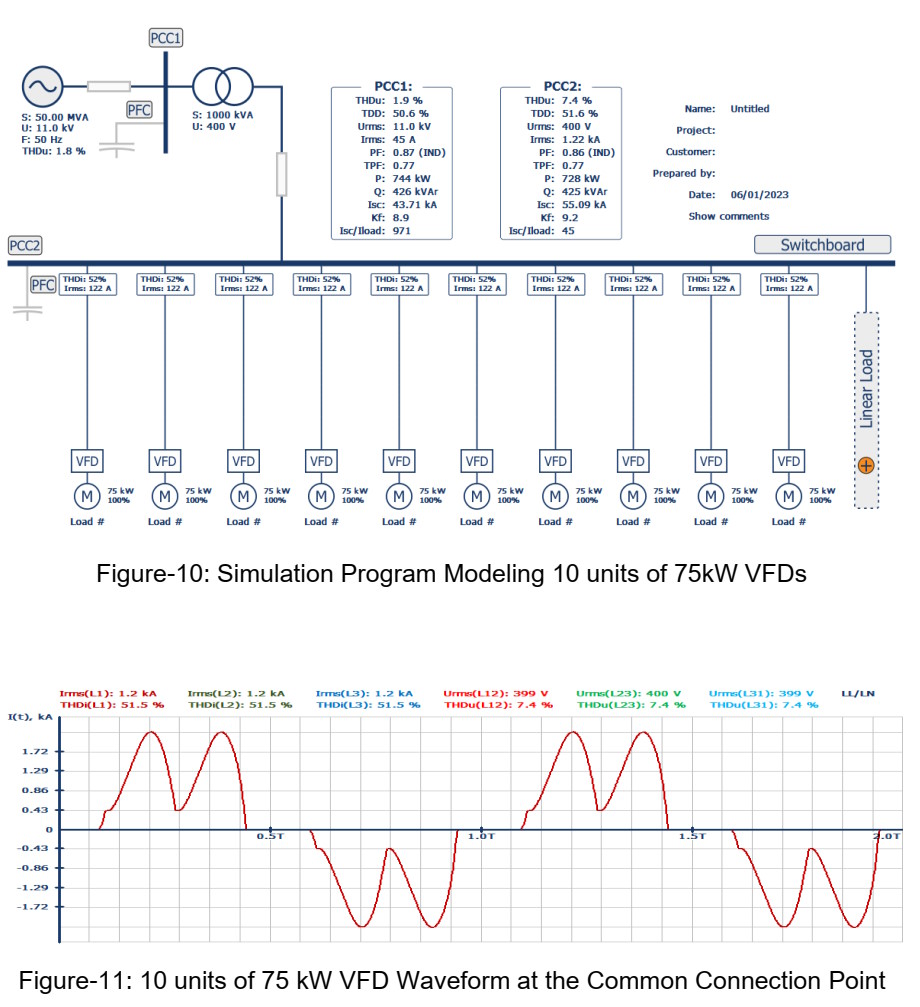
Tests were performed in the lab using a 75kW 400V 50Hz speed control device to analyze the impact of directly connecting multiple variable frequency drives to the grid. Simulation software was utilized to examine the total harmonic distortion ratio that would result from this connection.
The simulation program evaluated the harmonic effects of ten units of 75kW variable frequency drives, comparing the total current harmonic distortion ratio at the common connection point between direct connection and when a passive serial filter is added in front of each VFD.
The results are illustrated in Figure-11, depicting the total harmonic current distortion ratio at this common connection point for all ten units.
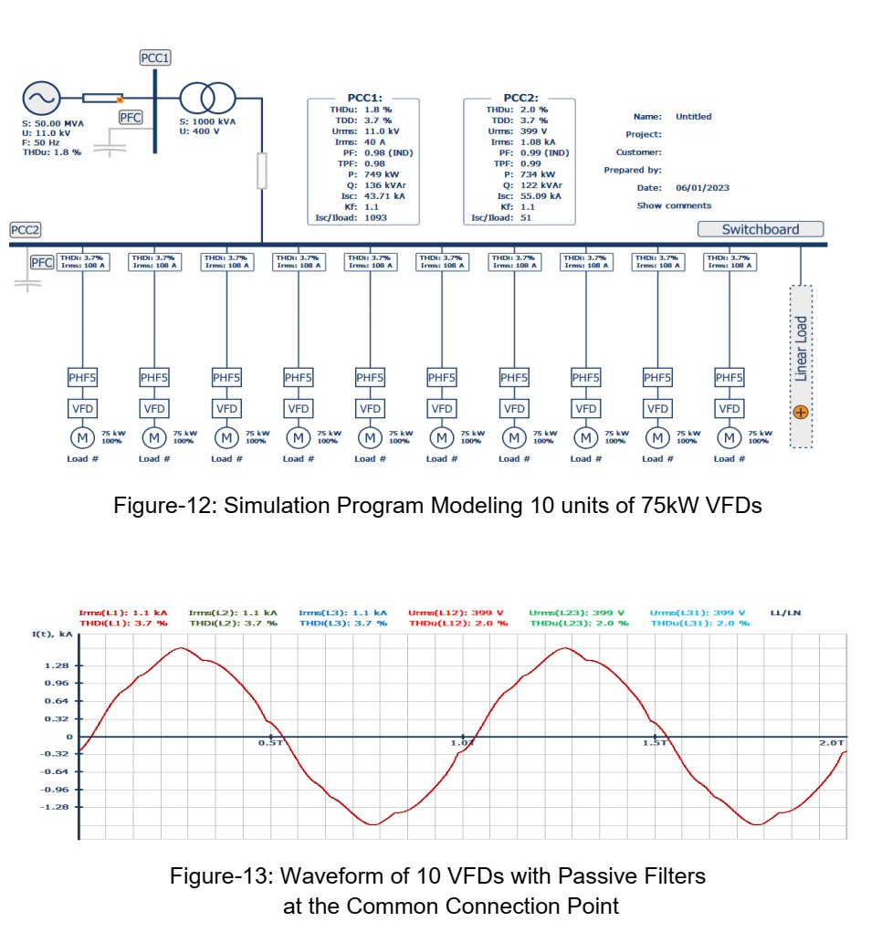
When a serial passive filter is connected to the input of 10 units of 75kW 400V 50 Hz variable frequency drive, the total harmonic current distortion ratio at the common connection point is shown in Figure-12.
 FINAL OUTCOME
Based on our power quality measurements in industrial zones, we have observed a consistent increase in power grid total harmonic distortion every year in our country.
Despite the relatively low power levels (in the order of kW), the widespread use of power electronics devices, such as variable frequency drives, in industries is a significant contributor to this issue. Intervening at the input of each variable frequency drive to reduce the flow of current harmonics into the grid is expected to lead to substantial improvements in power grid total harmonic distortion. We attempted to validate this hypothesis through testing methods and simulation programs.
REFERENCES
[1] Arillaga J., Smith B.C., Watson N.R., & Wood A.R., “Power System Harmonic Analysis,” John Wiley 1997
[2] Ergun Elektrik, Product Catalogue , https://ergunelektrik.com/wpcontent/uploads/2023/04/ergun-elektrik-katalog_TR_2023-min.pdf
[3] Harmonix, Serial Passive Harmonic Filter Simulation Software [6] Rock well Automation Mequon, WI, Straight Talk About PWM AC Drive Harmonic Problems and Solutions.
[4] Harmonix, Serial Passive Harmonic Filter Simulation Software
Didem Ergun Sezer
Elektrik Mühendisi
Ergun Elektrik A.Ş. İzmir
didem@ergunelektrik.com